Flip-Flop with LED Display
The purpose of this project is to see how a display readout can be controlled by a free-runing multivibrator or "flip-flop". This type of control is used in most hand calculators but at such a high rate of speed that you can't see the numbers flicker. It is also used in some equipment as a logic circuit clock pulse generator.
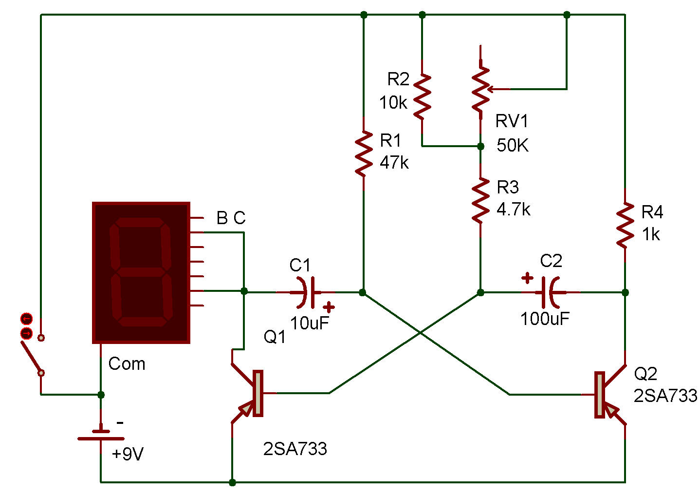
Flip-flops have many applications in electronics. This flip-flop (or free-running multivibrator, as this circuit is more often called) uses two Transistors, two Capacitors and four Resistors to accomplish a variable-speed ON-OFF control of the LED. The LED is wired to flash the number "1".
The Transistors are always in opposite states, when the 2SA(1) is ON, the 2SA(2) is OFF and when the 2SA(2) is ON, the 2SA(1) is OFF. The changes of states from ON to OFF and OFF to ON is accomplished very fast (in microseconds) because of regenerative feedback between the two Transistors.
Changing from one state to the other is called the "flip", and then changing back to the original state is called "flop". This flip-flop action may be explained as follows:
Recall that a Transistor which is ON acts as if it has a short circuit between C-E, and when it is OFF it acts as if it has an open circuit between C-E. Also, notice that base-biasing Resistors are provided for both Transistors so that if no feedback were provided from the Capacitors, both Transistors would be ON.
Obviously, the function of the Capacitors is to hold alternate Transistors in the OFF state.
Let's start an assumed circuit operation with the 10uF holding the 2SA(2) in the OFF state. The 2SA(1) is then ON and the 100uF is charged quickly through its series 10K Resistor and B-E junction of the 2SA(1), by the Battery.
The 4.7K and 50K Control keep the 2SA(1) in the ON state after the 100uF is charged up. At this time the charge which is on the 10uF is slowly discharging through the 47K Resistor, Battery and C-E elements of the 2SA(1).
Remember, the 2SA(1) is ON, and its C-E elements act like a short circuit. The voltage on this Capacitor maintains a reverse-bias on the 2SA(1) as long as the charge is sufficiently high.
Before the 10uF is completely discharged, the low C-E voltage of the 2SA(1) allows the negative voltage from the 47K to turn the 2SA(1) ON.
The instant the 2SA(2) is turned ON, the 100uF quickly turns the 2SA(1) OFF. With the 2SA(1) OFF, its collector voltage is allowed to rise toward the 9V of the Battery. As this occurs, the LED is turned OFF, and through the fast charging of the 10uF, the 2SA(2) is turned full ON. This change in state of "flip" occurs very quickly (microseconds).
After a while the charge on the 100uF is decreased to where it can no longer hold the 2SA(1) OFF, and the circuit "flops" back to the original state to begin the above action, again.
Adjust the 50K Control throughout its range and notice the effect on LED flashing rate.
Use your VOM to measure Capacitor voltages, Transistor voltages and LED voltage while the circuit is operating. The slow rate of flashing should allow you to correlate the VOM readings with circuit opeation.
Can you now explain circuit operation to someone else without referring to any notes?
If you can, you have come a long way. This circuit seems very complicated until you study it for a while.
You can verify the circuit operation by temporarily short circuiting the B-E junctions of first the 2SA(1) and then the 2SA(2). This holds the shorted Transistor in the OFF state in place of the charged Capacitor.

![]()