D-latch
74HC00, 74HC02
Let's experiment with a D flip-flop circuit with a latch function. The latch is a kind of memory function, so this circuit can store data produced at a certain moment. Just in case you forget, D flip-flop stands for "delay flip-flop."
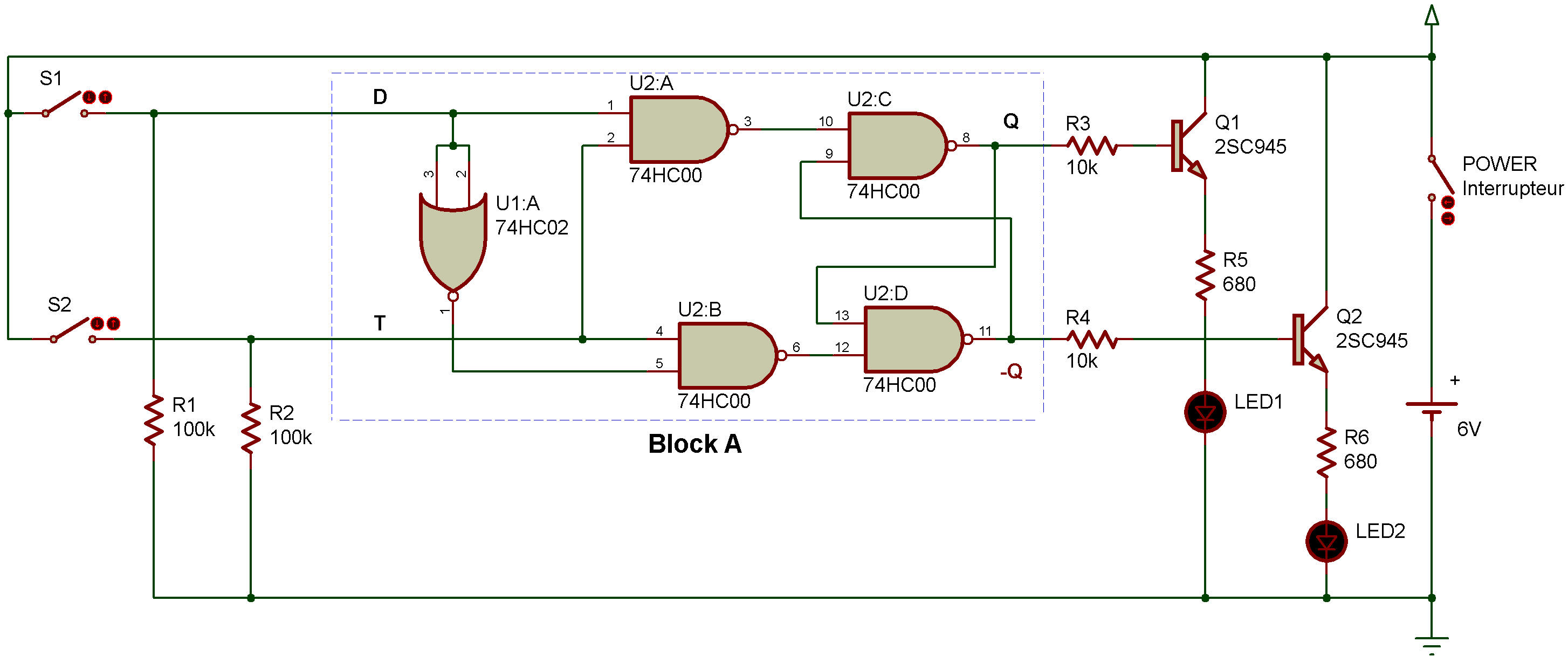
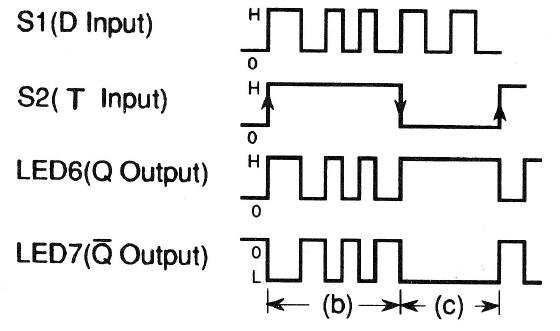
As you'll see from block B of the schematic, this D flip-flop circuit is made up of D (data terminal). T (clock terminal), and two output terminals Q and Ǭ. It works by the ON/OFF operation of S1 and S2 as shown in Figure 1.
In this project, the output level is 1 when the LED is ON and 0 when it is OFF.
When you finish wiring the circuit, turn power ON, and you'll notice LED 1 or LED 2 light up.
a) Turn S1 ON and OFF with S2 released, and the LED stays ON.
b) Turn S1 ON and OFF while pressing S2, and LED 1 and LED 2 take turns blinking.
c) Now, release S2 after LED 1 is lit, then turn S1 ON and OFF, and you'll see LED 1 stay ON.
d) Now press S2, and LED 1 goes out and LED 2 lights up.
Where in the above operation do you think data is stored?
It's stored when you come to step c). The circuit doesn't accept the signal from S1 once it stores data at this step. Try to figure out why it works this way by checking its function with Figure 1.

![]()