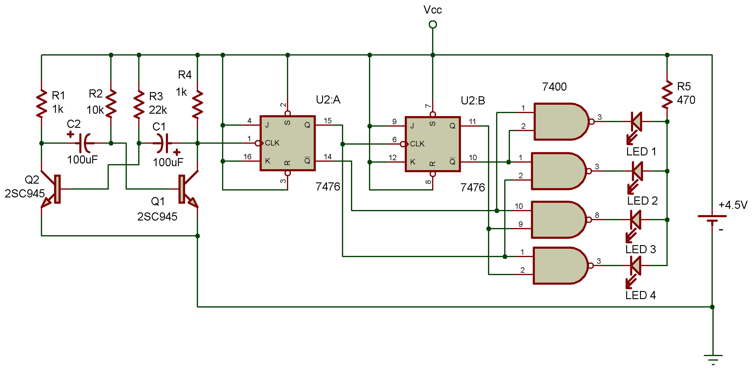
Divide by 4 counter with line decoder
7400, 7476
We can use the same line decoder arrangement that we used in Project Counter with line decoder with a divide by 4 counter circuit.
This Project will let you see how it's done. You'll notice that a transistor multivibrator circuit is used in this Project.
When you put the power ON, the four LEDs will light up one after another as the circuit counts each pulse from the multivibrator.
The counter is an asynchronous type and the Q and Ǭ outputs of both, are input into the line decoder arrangement. You'll notice that each output serves as one of the inputs for two different NANDs. And the Q output of the first flip-flop is also the clock input for rhe second flip-flop.
Ever wonder what would happen if you added another flip-flop to this circuit? The first flip-flop "divides" the input into two outputs (Q and Ǭ). The second flip-flop adds two more outputs. Do you think the third flip-flop would give you a total of six outputs? Guess again .., it would give you eight outputs!
When flip-flops are connected in a "master and slave" arrangement, the outputs, aren't added together — they're multiplied. In a counter with two flip-flops, multiplying the outputs of both gives 2 x 2, or 4. With three outputs, the result of multiplying the outputs of all three is 2 x 2 x 2, or 8.
If we were to connect four flip-flops together in a circuit like this, we would have 16 different outputs (you know why, don't you?).
And since the counter could have up to 8 or 16 different outputs, it could count up to 8 or 16. Today's large computers are able to count and handle large numbers using more complex versions of the circuit in the Project. (Of course, the counters in computers are synchronous so that all the flip-flops can "march in step!")

![]()