74HC595 Shift-Registers
Arduino (Kuman / Keyestudio)
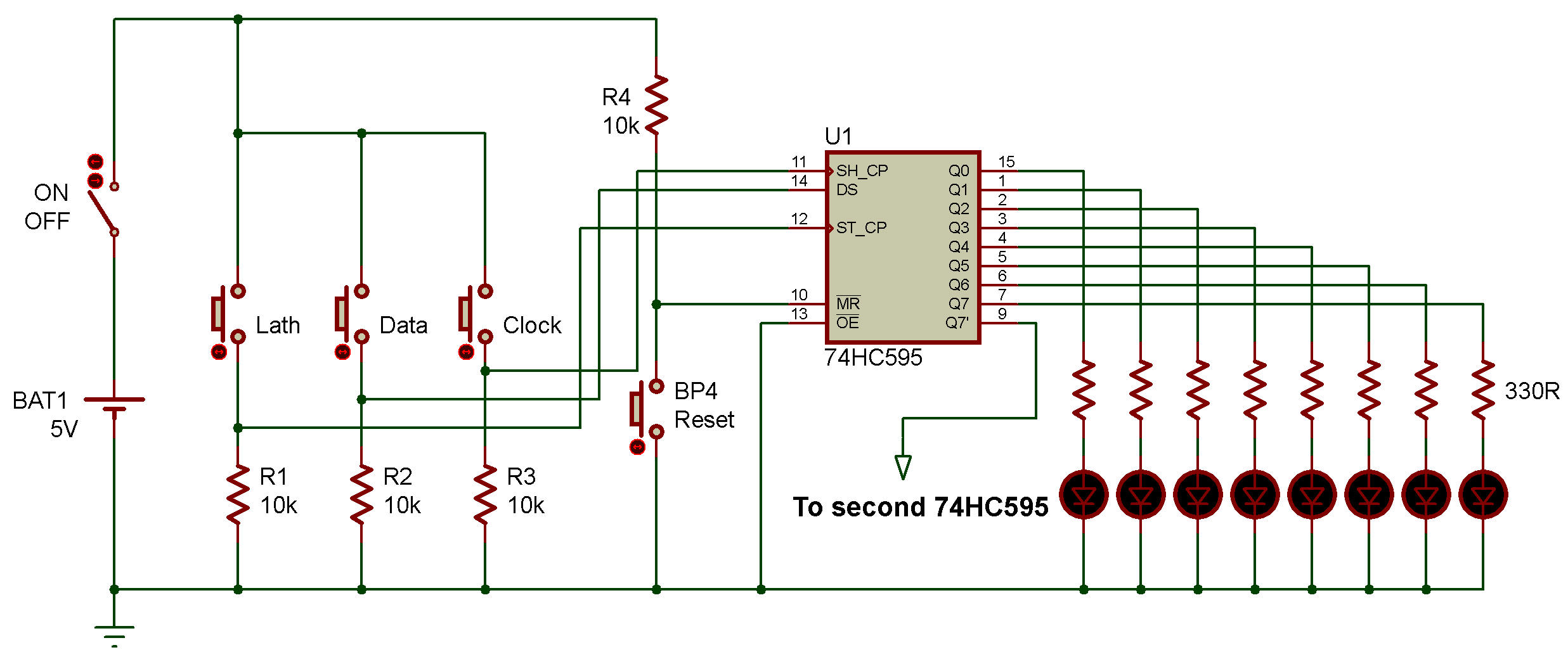
Manual Test Circuit
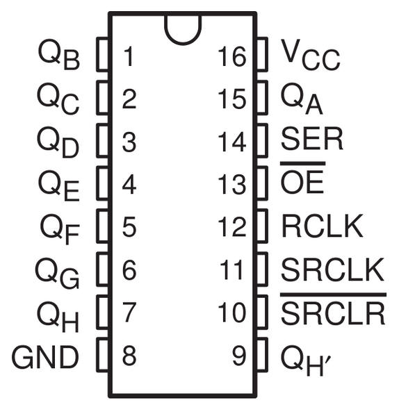
| Pin | Description | Function |
| QA-QH | Output pins | Outputs of the shift register |
| VCC (Pin 16) | Power | Positive voltage for the shift register |
| GND (Pin 8) | Power | Ground for the shift register |
| QH' (Pin 9) | Serial Out | Serial out is used to shift data to another 74HC595 shift register |
| Master Reclear, active low | This sets all the bits in the shift register to 0 or off if pulled LOW. | |
| Shift Clock (Pin 11) | Shift Register Clock Pin | If pulled HIGH, this shifts all the values in the shift register forward one. |
| Latch Clock (Pin 12) | Stroage Register Lock Pin | When pulled HIGH, it outputs the new shift register values. |
| Output enable, active low | This enables the output when grounded and disables it when high. | |
| Serial Data Input (Pin 14) | Input for New Serial Data | This is the input pin for the new serial data. |
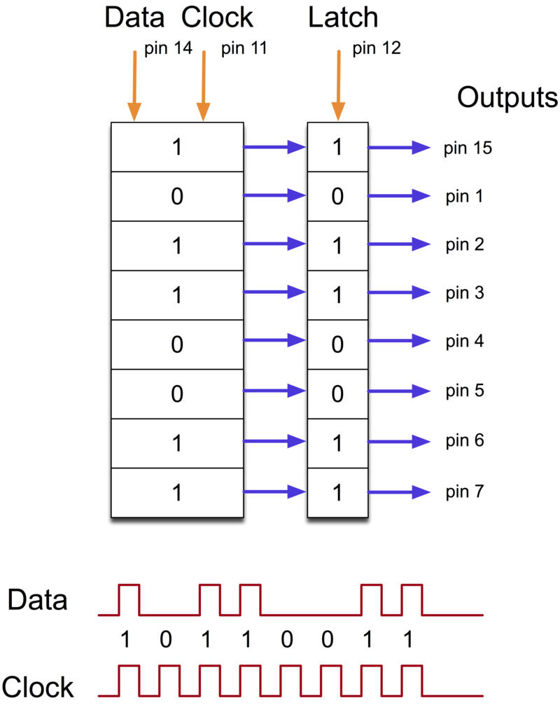
The 595 has two registers (which can be thought of as “memory containers”), each with just 8 bits of data.
The first one is called the Shift Register. The Shift Register lies deep within the IC circuits, quietly accepting input. Whenever we apply a clock pulse to a 595, two things happen:
The bits in the Shift Register move one step to the left.
For example, Bit 7 accepts the value that was previously in bit 6, bit 6 gets the value of bit 5 etc. Bit 0 in the Shift Register accepts the current value on DATA pin.
At the rising edge of the pulse, if the data pin is high, then a 1 gets pushed into the shift register. Otherwise, it is a 0.
On enabling the Latch pin, the contents of Shift Register are copied into the second register, called the Storage/Latch Register.
Each bit of the Storage Register is connected to one of the output pins QA–QH of the IC, so in general, when the value in the Storage Register changes, so do the outputs.
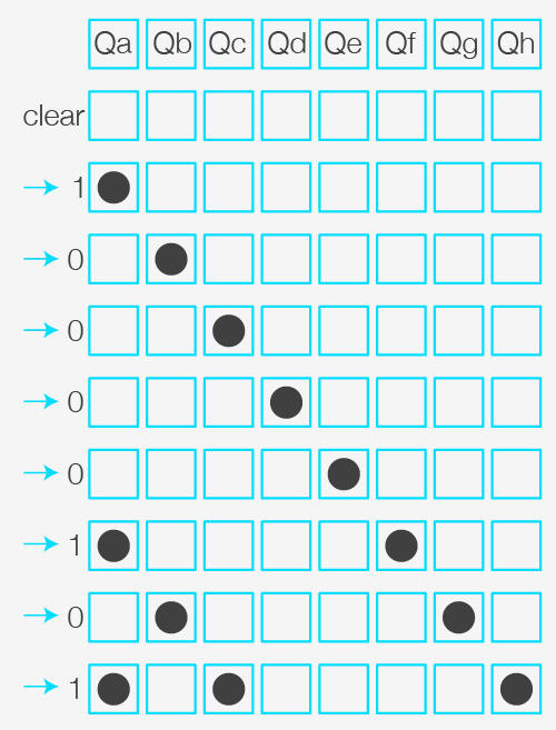
Let's try to enforce the use of a Shift Register on 8 Leds.
Imagine that we want to turn on LEDs 1, 3 and 8.
First, we will turn off all the LEDs (Clear, via the SRCLR pin), we will pass all registers to 0.
Then, we pass the first value in High then we shift by 4.
Then we again pass the first value in High then we shift by 1.
Finally we again pass the first value in High.
One of the advantages of the Shift Registers is that they have a pin called RCLK (Register Clock) which allows you to make no changes as long as it is kept in LOW.
So as long as RCLK is at LOW you can assign the values you want to the 8 output pins without the display changing.
Once you have set the correct values for your output pins, all you have to do is change RCLK to High and the Shift Register 74HC595 will display the changes.
We can thus modify our different registers several times (in 8 steps for example), but we will only see one modification, which will suggest that everything was done in one step.

![]()